Security Camera Power Supply Guide
In modern security systems, the power supply for surveillance cameras is a crucial link in solution planning and construction installation. Understanding power interfaces, specifications, and the characteristics of various power supply methods can not only ensure the smooth and efficient completion of projects but also avoid equipment malfunctions and instability. This article will provide a comprehensive analysis of camera power supply knowledge, covering both home and engineering cameras.
I. DC Round Plug Power: The Most Traditional Power Method
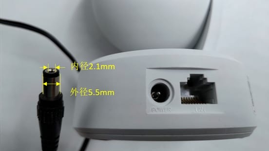
Most home and some engineering cameras use DC round plug power. This interface may look simple, but it has precise specification requirements.
Common DC Interface Specifications:
- Plug outer diameter: 5.5mm (tolerance ±0.05mm)
- Plug inner diameter: 2.1mm (tolerance -0/+0.1mm, i.e., 2.1-2.2mm)
- Polarity configuration: Inside the power adapter plug is positive, outside is negative; conversely, for the camera interface, inside is negative, outside is positive
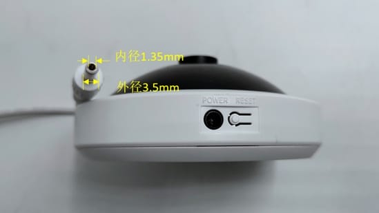
Special DC Interface: Panoramic cameras (fisheye cameras) use a smaller DC interface:
- Outer diameter: 3.5mm (tolerance ±0.05mm)
- Inner diameter: 1.35mm (tolerance -0/+0.1mm)
- Polarity configuration is the same as the common adapter
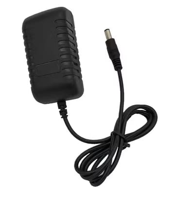
Power Principle: The 220V AC (Alternating Current) used in homes needs to be converted into DC (Direct Current) by a power adapter to supply power to the camera. The characteristic of direct current is that the direction of the current is constant and unchanging, making it very suitable for electronic devices.
💡Physics Mini-Class
- Direct Current (DC): Current always flows in one direction, and the polarity of voltage and current remains unchanged. Common in battery-powered devices such as flashlights, mobile phones, etc.
- Alternating Current (AC): The direction and magnitude of the current change periodically, usually represented as a sine wave. Homes and industrial electricity mainly use alternating current, with common voltages of 220V or 380V.
Household power is 220V AC, which needs to be converted to DC via a power adapter. As long as the output voltage of the power adapter meets the camera’s requirements, it can supply power normally; it belongs to general-purpose equipment.
II. PoE Power: Modern Smart Choice
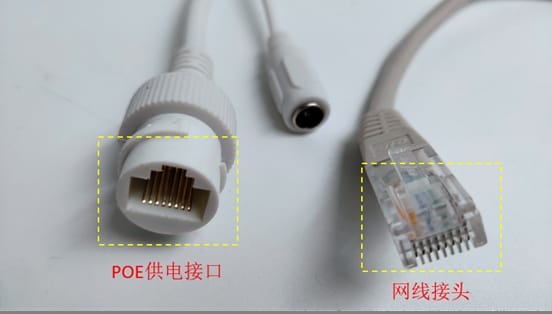
PoE (Power over Ethernet) is a technology that transmits data and electrical energy simultaneously through a network cable. It is widely used due to its simplicity, safety, and standardization.
Standard PoE Power:
- Powers via the 1236 or 4578 cores of the network cable
- 1236 cores transmit data simultaneously
- Complies with IEEE 802.3af and IEEE 802.3at power supply standards
- Wide applicability and strong compatibility
Non-Standard PoE Power:
- Directly provides fixed voltages of 12V, 24V, 48V, or 54V
- Does not care if the terminal device supports PoE
- Requires matched custom equipment and cannot be mixed casually
- For example, TP-Link’s TL-IPC5Y36F-A only supports Passive PoE power
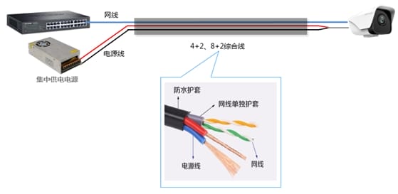
III. Centralized Power: The Preferred Solution for Large Projects
In security construction, centralized power solutions can unify control and management of power supply, reducing engineering cable usage.
However, centralized power often suffers from insufficient power supply, causing IPCs to fail to start or restart frequently at night. Solutions include:
- Appropriately increase the power output voltage (adjust with a screwdriver at the +V ADJ position).
- If using a network cable for power supply, use a 2+2 power method where cores 4 and 5 are twisted together as the positive pole and cores 7 and 8 are twisted together as the negative pole to reduce impedance.
- Replace with power cables of better material and thicker wire gauge (such as pure copper/0.75mm).
IV. Understanding Power Supply Specifications
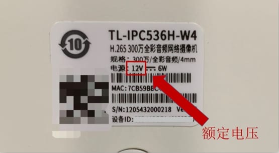
The label on the camera indicates the operating voltage and power requirements, which is the key basis for selecting a power adapter.
Voltage Requirements: Cameras usually have three operating voltage specifications: 12V, 9V, and 5V. The power adapter voltage must match the device’s rated voltage. You cannot use a 5V adapter to power a 12V camera, nor can you use a 12V adapter to power a 5V camera.
Power Requirements: According to the formula: Rated Power = Rated Voltage × Rated Current
For example: If the device rated voltage is 12V and rated power is 6W, the selected power adapter must be no less than 12V/0.5A. To ensure stable operation, a 12V/1A adapter is recommended.
If the voltage is consistent, the current can be greater than the rated current. If the current is excessive: the device will draw power as needed and will not be damaged by the adapter’s high current (it only wastes energy).
Power Adapter Selection Core Parameter Comparison Table
| Selection Dimension | Core Requirement | Common Misconception | Risk Consequence |
|---|---|---|---|
| Output Voltage | Must be fully consistent with the device rated voltage (e.g., 12V device with 12V adapter) | Think “voltage higher than rated value is also OK” or “just avoid voltage being too low” | Too high: Breakdown of electronic components, device burnout, even causing short circuit/fire; Too low: Device cannot start, unstable operation (stuttering/disconnection), long-term operation damages circuit |
| Output Current | Adapter rated current ≥ Device rated current (e.g., device needs 2A, choose adapter 2A or above) | Pursuing “the higher the current, the better” or “current slightly lower than device is also OK” | Insufficient current: Insufficient power supply, device cannot work normally; Excessive current: Device draws power as needed, will not be damaged by high adapter current (only wastes energy) |
| Interface Polarity | Must fully match the device interface polarity (e.g., inner positive outer negative / inner negative outer positive) | Ignore polarity markings, connect randomly | Reverse connection directly burns out internal circuit of device, irreparable |
| Interface Specification | Adapter interface size (diameter/plug type) fully fits device interface | Use “can plug in” as judgment criteria, ignore looseness issues | Poor contact causes device power interruption, abnormal operation, long-term looseness may cause heating |
Supplementary Key Instructions
- Voltage is a “Hard Match Item” with no room for error; it must precisely correspond to the device rated voltage (e.g., 5V device must not use 9V/12V adapter).
- Current is a “Lower Limit Match Item”; the adapter current can be higher than the device demand, but cannot be lower, otherwise it will cause device failure due to insufficient power.
- Polarity is usually marked on the device power interface or adapter (e.g., “Inner + Outer -”); be sure to check before connecting.
Device and Adapter Matching Checklist
| Check Step | Check Content | Qualified Standard | Check Method | Remarks |
|---|---|---|---|---|
| 1 | Device Rated Voltage | Adapter output voltage is fully consistent with device rated voltage (e.g., 12V device must be paired with 12V adapter) | Check “Rated Voltage” on device nameplate/manual, compare with “Output Voltage” on adapter casing | Mismatched voltage is directly disqualified, no room for error |
| 2 | Device Rated Current | Adapter output current ≥ Device rated current (e.g., device marked 0.5A, adapter needs ≥0.5A) | Read device “Rated Current/Operating Current”, confirm adapter “Output Current” meets lower limit requirement | Current can be slightly higher, will not damage device, only provides power margin |
| 3 | Interface Polarity | Adapter polarity is fully consistent with device requirements (inner positive outer negative / inner negative outer positive) | Check markings next to device power interface (e.g., “+”, “-” symbols), compare with polarity markings on adapter casing | Wrong polarity will directly burn the device, must focus on verification |
| 4 | Interface Specification | Adapter interface size, plug type fully fits device interface | Actual plug-in test (must be firm and not loose), or check device interface diameter (e.g., 5.5mm×2.1mm) | Looseness will lead to power interruption, heating; interface mismatch requires changing connector (ensure polarity unchanged) |
| 5 | Power Type | Adapter type (DC DC/AC AC) is consistent with device requirements | If device marked “DC Input”, select DC adapter; avoid using AC adapter for direct power supply | Most electronic devices (like cameras) require DC power |
| 6 | Extra Function Adaptation (if any) | When device needs special power functions (e.g., POE, wide voltage adaptation), adapter must support corresponding functions | Check device manual for special power requirements, confirm adapter function match | Without special requirements, satisfying the first 5 items allows normal use |
Usage Instructions
- Check item by item; only if every item meets the “Qualified Standard” is it compatible. If any item fails, it cannot be used.
- When checking, prioritize viewing the device nameplate and adapter casing markings; if information is blurry, consult the product manual.
- If replacing the connector (e.g., interface size mismatch), only the physical interface can be replaced; strictly prohibited from changing core parameters such as voltage and polarity.
V. Special Scenario Power Solutions
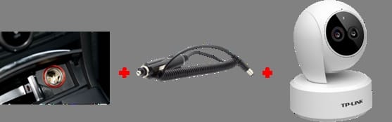
Vehicle Power:
- Small vehicles: Via cigarette lighter charging port to DC power
- Large vehicles: Use dedicated battery output for stable DC power
- Note: Large transport trucks are usually 24V, small cars are usually 12V. 24V needs a step-down converter to transform into 12V to power most cameras.
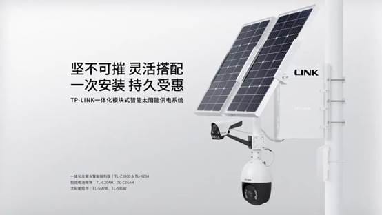
Solar Power: Solar power systems (such as TL-ZJ800 & TL-K234) output 12V DC power, with a maximum output current of up to 5A, meeting usage in multiple scenarios.
Precautions: Current solar power systems can power up to three loads. The built-in DC-DC circuit provides voltage regulation, outputting a stable 12V.
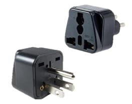
Powering Abroad: When using monitoring equipment in different countries, pay attention to differences in power interfaces and specifications:
- For devices requiring 12V DC power, use a local power adapter to provide 12V.
- For devices requiring AC mains power, interface and voltage adaptation is required.
- Two-hole plug devices usually support 110V-240V wide voltage and can be used with American sockets.
- For devices specifying 220V power, you need to connect to an inverter to convert the voltage to 220V.
- For three-hole 220V devices, a US standard conversion plug is required before connecting to the inverter.
VI. Common Questions and Answers
1. What is the general distance of a camera’s power cord, and are extension cables supported? Usually, camera power cords come in 3m and 5m specifications and support external DC extension cables. It is recommended to use 0.5mm oxygen-free copper or better wire to reduce line loss.
2. How to use standard PoE power for non-PoE cameras? You can use a PoE splitter to separate the power and data signals transmitted over a standard PoE line into DC power and a network interface, providing access for non-PoE cameras.
3. If a camera supports both DC and PoE, what is the power priority? For IPC products, there is no clear power priority; whichever power method has the higher voltage will be used to power the device.
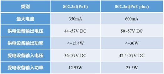
4. What are the standard voltages, currents, and power for IEEE 802.3af and 802.3at?
| Standard | PSE Power | Voltage Range | Max Current |
|---|---|---|---|
| IEEE 802.3af | 15.4W | 44-57V | 350mA |
| IEEE 802.3at | 30W | 50-57V | 600mA |
Conclusion
Camera power supply is a foundational link in security surveillance systems that cannot be ignored. Choosing the appropriate power method, understanding various interface specifications, and knowing countermeasures for special scenarios can not only ensure the stable operation of the surveillance system but also improve construction efficiency and quality. We hope this article provides practical reference value for your engineering projects.